Preparing reliability block data
The table a reliability block diagram needs: one row per connection naming the next block, the columns and what to call them, series, parallel, standby and m-out-of-n structures, and a complete worked example.
One row per connection, naming the next block
Each row names a block and, in Connected Node ID, the block it leads to. A block that leads to several blocks, such as the point where parallel paths split, has one row for each. The output's row leaves Connected Node ID blank.
Values on a row describe that row's block. When a block has several rows, give them the same values; rows that disagree are reported, and the first row's values are used. Relationship Type on a row describes the connection from that block to the next.
The input
One row leading to the first block.
Each block in series
One row leading to the next block.
A parallel split
One row for each path, leading to the first block of that path.
The end of each parallel path
Its last block leads to the block or junction where the paths merge.
An m-out-of-n block
Each of its n blocks leads to it. Its own row carries Vote Threshold (m) and Vote Input Count (n).
The output
One row with Connected Node ID left blank.
Columns
| Column | Maps to | Well | Fill it in on |
|---|---|---|---|
| Node ID | Node ID | Data fields | Every row. |
| Connected Node ID | Connected node | Data fields | Every row except the output. |
| Node Type | Node type | Data fields | Every row. |
| Label | Label | Data fields | Every row. |
| Relationship Type | Relationship type | Data fields | Optional. A blank cell is a series path. |
| Order | Order | Data fields | Blocks that sit side by side, such as parallel paths, to set their order from the top. |
| Reliability | Reliability | Values | Any block. |
| Availability | Availability | Values | Any block. |
| Failure Rate | Failure rate | Values | Any block. |
| Status | Status | Data fields | Any block, for colouring and the summary strip. |
| Vote Threshold | Vote threshold (m) | Values | The m-out-of-n block's row. |
| Vote Input Count | Vote input count (n) | Values | The m-out-of-n block's row. |
| Diagram ID | Diagram ID | Data fields | Every row, when the table holds more than one diagram. |
| Diagram Name | Diagram name | Data fields | Every row, for a readable name in the diagram picker. |
Only Node ID has to be mapped. Any other column, such as an asset ID, an MTTR or a last tested date, needs no mapping.
Other column names that bind
| Role | Also recognised |
|---|---|
| Reliability | R |
| Availability | Uptime |
| Failure rate | Lambda, Rate, Hazard Rate |
| Vote threshold (m) | Required Count, Required Blocks, Required Channels, Threshold, Minimum Votes, M, K |
| Vote input count (n) | Total Count, Total Blocks, Total Channels, Total Inputs, Vote Inputs, N |
These bind only to number columns. A name with a unit added, such as Failure Rate per Hour, does not bind; call the column Failure Rate, or map it by hand on the Data Mapping tab. A % sign is ignored, so Availability % binds.
A complete example
A cooling water supply: a power supply, a duty pump with a standby pump in parallel, a heat exchanger train, and three temperature transmitters voting two out of three. It validates with no errors or warnings. Reliability, Vote Threshold and Vote Input Count are in Values, set to Don't summarize. Cells with no value are left blank.
| Node ID | Connected Node ID | Node Type | Label | Relationship Type | Order | Reliability | Vote Threshold | Vote Input Count | Status |
|---|---|---|---|---|---|---|---|---|---|
| IN | PSU | Input | Cooling demand | ||||||
| PSU | SPLIT | Component | Power supply PSU-1 | 0.998 | Healthy | ||||
| SPLIT | PMP-A | Parallel Junction | Pump split | Parallel | |||||
| SPLIT | PMP-B | Parallel Junction | Pump split | Standby | |||||
| PMP-A | MERGE | Component | Duty pump P-101A | 1 | 0.95 | Healthy | |||
| PMP-B | MERGE | Standby Component | Standby pump P-101B | 2 | 0.93 | Degraded | |||
| MERGE | HX | Parallel Junction | Pump merge | ||||||
| HX | TT-1 | Subsystem | Heat exchanger train | 0.99 | Healthy | ||||
| HX | TT-2 | Subsystem | Heat exchanger train | 0.99 | Healthy | ||||
| HX | TT-3 | Subsystem | Heat exchanger train | 0.99 | Healthy | ||||
| TT-1 | VOTE | Component | Temperature transmitter TT-1 | 1 | 0.985 | Healthy | |||
| TT-2 | VOTE | Component | Temperature transmitter TT-2 | 2 | 0.985 | Healthy | |||
| TT-3 | VOTE | Component | Temperature transmitter TT-3 | 3 | 0.985 | Failed | |||
| VOTE | OUT | Voting | Trip logic | 2 | 3 | ||||
| OUT | Output | Cooling delivered |
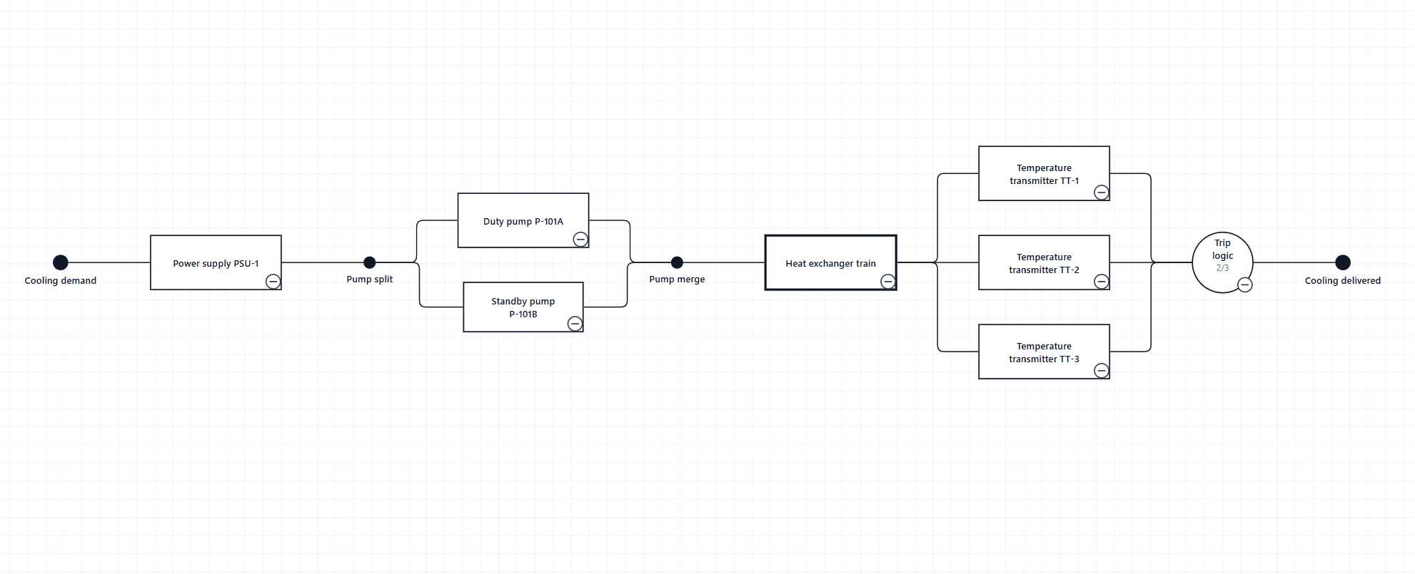
Pump split has one row per path, and its second row is a Standby path, drawn green and dashed under the Custom profile. Heat exchanger train has one row for each transmitter it leads to, with the same values on all three. Trip logic needs two of its three transmitters, and 2/3 is written under it.
Parallel paths, with or without junctions
The split and merge can be Parallel Junction rows, as in the example, drawn as small dots. They can also be left out: the block before the paths leads to the first block of each path, and the last block of each path leads to the block after. Either way the paths stay side by side, in Order from the top.
m-out-of-n blocks
- Vote Threshold (m) is how many of the block's inputs must work. Vote Input Count (n) is how many feed it.
- m must be a whole number of 1 or more, and no more than n.
- n is checked against the number of blocks that actually lead to the block.
- With both mapped, m/n is written beneath the block, unless its label or secondary label already says it, as in 2/3 compute capacity.
If your table names the previous block
Set Data Mapping → Connection column → Reads as to Connected node comes before this row. Left on the default, such a table is read backwards, and the Validation tab reports No complete path connects the input side to the output side., together with errors that the input has something leading into it and the output carries on into another block.
Without a Node Type column
Every block is read as a component. The block with nothing before it and the block with nothing after it are taken as the input and output, so the diagram still draws, but the last block is reported with Nothing leaves this block, so no path through it reaches the output. Map a Node Type column to name the input and output and to use the other block types.
Checks before binding the table
- Trim Node ID and Connected Node ID. An identifier that differs only by a space does not join.
- Give every row of a block the same values.
- Store reliability and availability the same way throughout, all as fractions or all as percentages. Nothing checks the range, and conditional formatting compares the stored number.
- Set Reliability, Availability, Failure Rate and the vote counts to Don't summarize.
- Use one Input and one Output.