Notation profiles
How a profile changes the drawing without changing the meaning, which settings a profile controls, and what switching profile does to your configuration.
What a profile does
A notation profile decides how a diagram is drawn: which symbol stands for each node type, how connectors are drawn, and which representational rules the drawing follows. It never changes what the diagram means. Node types, connections, the data mapping and Power BI selection are the same under every profile.
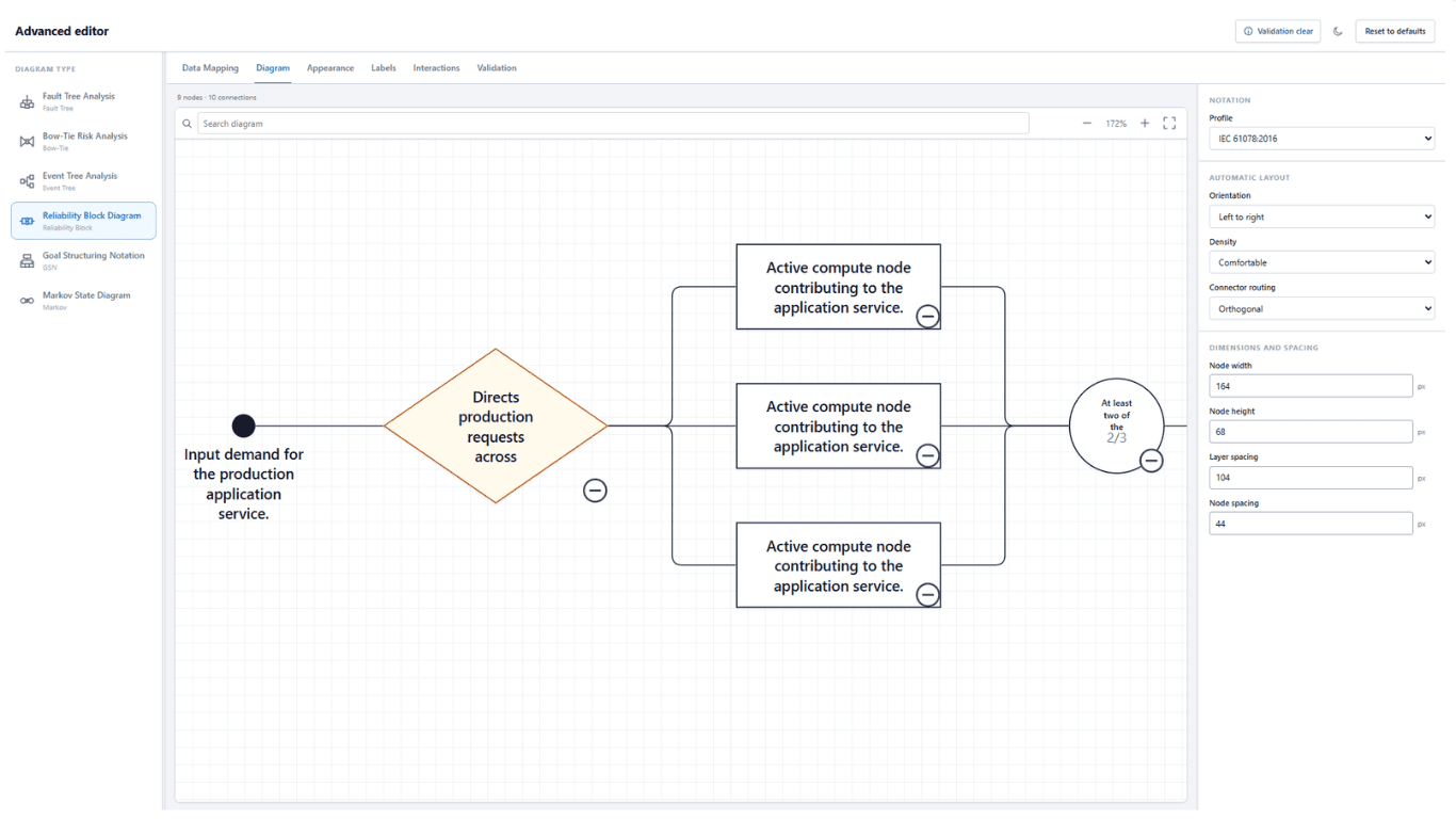
Choose the profile under Diagram → Notation → Profile. Switching needs no remapping.
Profiles by diagram type
| Diagram type | Profiles | New diagrams use |
|---|---|---|
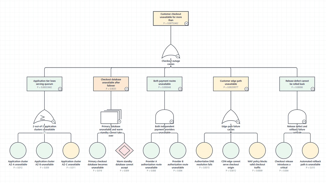
| Fault Tree Analysis | IEC 61025:2006, Traditional / NUREG-0492, Custom | IEC 61025:2006 |
| Bow-Tie Risk Analysis | None. No publication defines bow-tie symbols. | — |
| Event Tree Analysis | IEC 62502:2010, Custom | Custom |
| Reliability Block Diagram | IEC 61078:2016, Custom | Custom |
| Goal Structuring Notation | GSN Community Standard v3, Custom | GSN Community Standard v3 |
| Markov State Diagram | IEC 61165:2006, Custom | IEC 61165:2006 |
Many other standards describe these methods without prescribing how the diagram must look. Notation standards lists them, and which diagram type draws each.
Settings a profile controls
Under the active profile, every presentation setting is in one of three states. Hover a badge to see the reason.
| State | In the editor | Meaning |
|---|---|---|
| Fixed | Disabled, with Fixed by the notation profile | The profile owns the value. |
| Limited | Editable, with Limited by the notation profile | The value can be changed within bounds the profile sets. |
| Free | Editable, no badge | The profile assigns the setting no meaning. |
Under IEC 61025:2006, for example, symbol geometry and connector routing are fixed, border width is limited to 1–4 px, and colour, typography, spacing, orientation, labels and conditional formatting are free.
Rules that belong to a profile
Some rules come from a profile rather than from the method. A fault tree with no logic gates is reported under IEC 61025:2006, which requires gates, and accepted under Custom, which does not. The FDEP and Priority OR gates, which IEC 61025:2006 Annex A does not define, are available only under Custom.
Switching profile
Switching is non-destructive. Settings made under Custom, including symbol choices for each node type, stay in the configuration while another profile is active and apply again when you switch back.
Choosing symbols
Under Appearance → Node types, each node type has a Symbol dropdown listing Profile default, the notation's own symbols, and plain shapes. While a profile defines the symbol, the control is locked; set the profile to Custom to choose.