Probabilities, labels and symbols
Showing probabilities, failure rates and voting criteria on a fault tree, the summary strip and Node Inspector for fault trees, and the symbols drawn under each notation profile.
Fault tree values
These settings are in the Fault tree values group on the Labels tab.
| Setting | Options | Default |
|---|---|---|
| Probability display | Tooltip only, Secondary line, Hidden | Tooltip only |
| Probability format | Power BI format, Decimal, Percentage, Scientific | Power BI format |
| Probability decimal places | 0–6 | 3 |
| Failure rate display | Tooltip only, Secondary line, Hidden | Tooltip only |
| Failure rate format | Power BI format, Decimal, Scientific | Power BI format |
| Failure rate decimal places | 0–6 | 3 |
| Voting criterion | Tooltip only, Secondary line, Hidden | Secondary line |
| Voting criterion format | k/n, k-out-of-n (2oo3) | k/n |
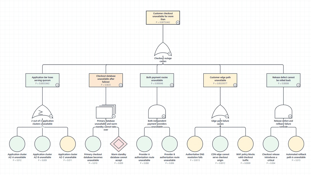
On the secondary line, values are written after any secondary label and separated by a dot, such as P = 0.012 and λ = 1.300e-6. Power BI format uses the column's format string from the model; decimal places apply to the other formats. Hidden also removes the value from tooltips.
Repair rate and mission time are shown in tooltips and the Node Inspector.
Sequence markers
Where an input to a Priority AND, Sequential, Priority OR or Spare gate has a priority sequence, its connector is labelled [1], [2] and so on. No setting is needed.
Summary strip
On a fault tree, the summary strip counts basic and dormant events together, and undeveloped events separately, by Status. Gates are not counted.
Node Inspector
The Analysis section lists the fault tree values mapped for the selected node. The Relationships section depends on what is selected.
| Selected | Relationships |
|---|---|
| A gate | Defines: the event above it. Inputs: the events beneath it. Condition: an attached conditional event. |
| An event | Output: the event above the gate it feeds. Through gate: that gate. Gate and Inputs: the gate beneath the event and that gate's inputs. |
| A transfer | Developed in or Referenced from: the linked diagram, with Open linked diagram. |
Colouring by status
Map a Status column, then add a rule under Appearance → Conditional formatting, for example Node fill when Status is Degraded. Turn on Labels → Legend → Show legend so readers can decode the colours.
Symbols under each profile
| Node type | IEC 61025:2006 | Traditional / NUREG-0492 |
|---|---|---|
| Top event, intermediate event | Rectangle | Rectangle |
| Basic event | Circle | Circle |
| Undeveloped event | Diamond | Diamond |
| Conditional event | Capsule | Oval |
| House event | Pennant | House |
| Dormant event | Double diamond | Double diamond, from IEC 61025 |
| Zero event | Slashed pennant | Slashed pennant, from IEC 61025 |
| AND, OR, INHIBIT gates | AND, OR, hexagon | AND, OR, hexagon |
| Exclusive OR, Priority AND gates | IEC symbols | Traditional symbols |
| Voting gate | Majority vote | OR body with a k/n marker |
| NOT, NAND, NOR, Sequential, Spare gates | IEC symbols | IEC symbols |
| Transfer in, transfer out | Wedges | Triangles |
| FDEP, Priority OR gates | Custom profile only | Custom profile only |
Under Traditional / NUREG-0492, a type the handbook has no symbol for is drawn with the symbol shown in the table, and the Validation tab notes each substitution.
Conditions are drawn as dashed connectors. A transfer connector is dashed with an arrowhead under IEC 61025:2006, and dashed without one under Traditional / NUREG-0492.
Custom symbols
Under the Custom profile, Appearance → Custom symbols sets a shape for a group of node types at once: Top and intermediate events, Basic events, Boundary events, Gates and Transfers. Boundary events are undeveloped, house, dormant, zero and conditional events.
Appearance → Node types sets the symbol for a single node type, from the IEC and Traditional symbols for that type or a plain shape.